Tolerances influence the cost, obviously. When developing products, tolerance management will get on your path at a certain moment. For rather simple designs this might not be a big deal. However, even here, a right approach could reduce costs or avoid surprises on costs later in the production. Once developing high precision structures, moving systems or complex product housings, you could gain a lot with the right approach. How can you manage tolerance to reduce costs and improve robustness of a system?

Value engineering starts early
Tolerances are often taken into account during the detailed design phase. This can force the mechanical designer to put in a lot of strict tolerances where they aren’t necessary. E.g. when there are too many separate parts in the tolerance chain, the wrong system components or production techniques are selected. So how should you do it?
When developing precise systems, thinking about tolerance in the detailed design phase is too late if you want to have an impact on final cost and manufacturability of a system. The big clue is to start with the full system architecture. Get to know the full system and all its limitations early in the project. What are the links between subsystems? What are the allowable tolerances of each subsystem? Once this is mapped, you can distribute the tolerances over the entire chain. Then you can do a feasibility check of all subsystems, by adding the interfaces and the standard tolerances of the predicted production technique. Next, check if these production techniques are still in line with the product and development target cost.
A basic principle of value engineering is to spread your tolerances in the chain to the most cost effectively manufactured parts or sub-systems.
Microfluidic systems are often defined by miniaturization and high mechanical tolerance specifications. A lot of read out devices for microfluidic cartridges are optical. Due to expensive wafer production, chip size matters to reduce cost. If the biological or chemical processes on this chip need to be analyzed using an optical system, this miniaturizing of the chip with its micro channels will implicate the need for higher precision and more expensive optics in the read out unit or device. Hence the positioning of the cartridge will get more critical too. Is the cost of the chip more important than the cost of the device?
In this type of developments it’s important to understand your business model, to know how to spread the costs. If for instance, you know from the start that revenue will come from selling microfluidic cartridges and the devices will not add a lot to the revenue stream, you should push the costs linked to tolerances towards the device. An option could be to put complex automated alignment and focus in the read out device, keeping in mind that the cost of the device will go up exponentially. But here you can keep the chip cost as low as possible. Option two is to distribute the tolerances over the different subsystems (chip, interfaces/alignment, read out system). This way you might not need an expensive automated alignment in the device, but the wafer chip needs to be bigger to be able to get a proper alignment and focus.
Easy design gains for the designer
Designs often need updates and iterations or even product generations to get to the wanted result. But there are simple tips and tricks that could help any designer make well-thought-out designs from the start.
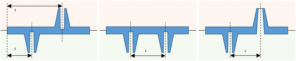
With precision molded parts there’s a simple reasoning that can help you to get more accuracy and reduce the cost of production. Here the job can be as simple as placing all functional features and interfaces on one side of the part. Accurate dimensions between features in one part of the mold are easier/cheaper than dimensions between 2 different mold parts. For example, the image below shows 2 features that need to be at a certain distance from one another. If the features are formed in opposite parts of the mold, there will need to be a reference to another position in the mold, adding an extra step in the tolerance chain (see image below). A solution is to put the features on the same side, like in the middle image. Obviously this is not always possible, however with this in mind, one can find ways to get features molded from the same side, like the center axes of the last image.
High tolerances don’t necessarily mean complex production techniques. Sheet metal can be the perfect choice to build robust and precise structures. When developing low quantity or intermediate precision devices, an old technique can be used to achieve relatively high accuracy. It’s known that 2D processing techniques, like laser/waterjet cutting or punching, have a high accuracy. With a groove and teeth principle it’s possible to make 3D structures that are precise and robust, even for large products.
The next image gives an example of such a structure. Here the device is a 695 x 370 x 460 mm automated lab instrument that needs accurate needle positioning over a big area.
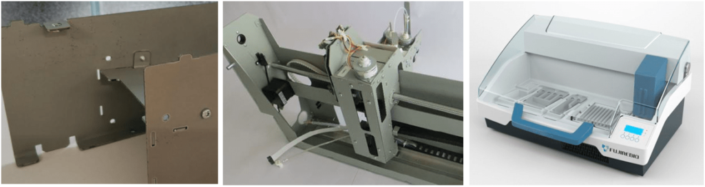
Due to the groove and teeth principle in separate 2D metal plates, the assembly is straightforward. There’s no need for calibration or assembly tooling in production and all necessary tolerances are achieved. So reducing the number of parts isn’t always the better solution. Bending sheet metal parts to reduce the number of parts wouldn’t give the same accuracy and would cause more fall out. Welding is most probably not a viable alternative as it often leads to warpage. When going for larger production batches, the next step would be to go with deep drawn sheet metal by hard tooling as seen in products like computers or printers.
As a last point, a recurring flaw we see when reviewing designs is over-constrained or hyperstatic designs. These often result in unpredictable behavior of the system, depending on how the device is placed in the field e.g. uneven ground. Similarly, environmental conditions like temperature, moisture, vibrations … need to be taken into account in order to achieve precision in a wide operating range. Key is to fix structures in a way they can expand and shrink in a controlled manner.
It all comes to preliminary mapping and understanding your system. If the criticalities around precision are mapped, it’s manageable to de-risk or avoid criticalities in subsystems. And with the appropriate design tricks, you can build a robust and accurate system from the start.
Download the perspective